Research Fellows
Mateusz Gugala
Early Stage Researcher at QMUL

I come from a small town in Poland - Kozienice, where I grew up. After high school I moved to the capital city of Poland and started my studies of Aerospace/Mechanical Engineering at Warsaw University of Technology in the Faculty of Power and Aeronautical Engineering. During my studies I was actively participating in student projects: Fuel efficient prototype and Formula SAE - WUTracing, as a member of the Student Association of Vehicle Aerodynamics - SKAP. My passion about engineering grew a lot at that time. Through the student projects I have learned how to work in a team and manage my time so that the final goals were well achieved. I have chosen fluid dynamics and in particular CFD as my specialisation, because it seems to be very challenging.
The main goal of the ABOUTflow project is to extend Adjoint based optimisation techniques for industrial application to unsteady flows. More particularly, my task is to work with the in-house CFD compressible solver mgOpt and focus on design parametrisation and mesh adaptation techniques for steady and unsteady optimisation cases. Mesh adaptation is an important subject for unsteady optimisation, as it allows to decrease the computational cost and keep the solution accuracy on the same level comparing to globally refined mesh.
Participating in the ABOUTflow project is a great opportunity to broaden my knowledge in CFD. The methods which are being developed are the next big step in industrial application of fluid flow simulation: the goal is not only to calculate the flow, but also to automatically modify the shape to optimise performance, minimise environmental impact. This is not just an academic tool but it
can solve complex technical problems: the participation of big industrial partners in About Flow confirms that those techniques are highly important for the future of industrial design.
The About flow project demands hard work, versatile skills development, and continuous improvement. All that needs to fit within tight time bounds, which is possible through intensive teamwork with people of versatile backgrounds and origins across the project. The possibility of exchanging knowledge in the international environment makes it even more inspiring and motivating. I am quite convinced, that this work is going to pay off for my future career and life and will be a significant contribution to the design processes of the future.
Objectives:
• Implementation of r-refinement algorithms, validation and benchmarking
• Extension of h-refinement schemes to unsteady flows
• Parallelisation of mesh-refinement including load-balancing
• Application of refinement algorithms to industrial test-cases
Contribute to Work Packages
Computational Fulid Dynmics is curently a standard tool used in design process in industry. Ability to analyse flows around shapes in virtual tunnels allow rapid technology development. However the current advancement reach the level where human prediction based purely on flow solution is no longer enough for further improvements. The Aboutflow project is focused on developing aerodynamic shape optimisation using computer algorithms. The gradient based methods with an efficient adjoint teechinique is being explored in order to push the design process to the new level. My research is focused on two main areas related to aerodynamic shape optimisation.
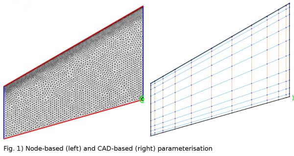
The first part is design parameterisation which is related to the choice of geometrical parameters that defines given shape. The first very natural one are the coordiantes of copmutational mesh for which the flow is copmuted. This method is called Node-based parameterisation. That is the reachest possible design space the optimisation can deal with. However results can often become noisy and not useful in real life unless the smoothing is applied. The other main technique is CAD-baed parameterisation. In thismethod design parameters are defined in CAD system (Computer Aided Design). The designer has a possibility to specify how reach the design space for optimisation will be. The parameters here can be for example b-spline/nurbs control points. The two parameterisation methods are presented on Figure 1 using the M6 wing example (left node-based, right CAD-based).
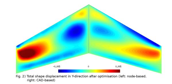
I used the wing transonic case example to run an optimisation using two parameterisation techniques described above in order to compare the resultant shapes. The mgOpt in-house solver was used for this puropose with steepest descent with Armijo line search optimiser. Both parameterisation approchaes shows similar results which was expected. The Figure 2 shows the comparison between total displacements of the geometry for both cases (left node-based, right CAD-based). The general trend is very simmilar although some diferences in details can be spotted, which is due to different parametersiation methods applied.
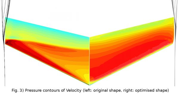
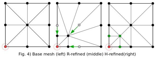 The second subject of my research are related to mesh adaptation methods and implementation for steady and unsteady adjoint CFD solver. I will consider the r-refinement (adaptation with keeping mesh size constant) and h-refinement (refinement by recursively subdividing mesh cells) schemes. The simple example of both refinement techniques is presented on Figure 4. For testing purposes I will apply the methodology to industrial and other benchmark test cases.
Introduction
Fluid dynamics is studied for decades, by thousands of researchers, PhD students and companies, and is a vital part of most technical systems, like aircraft, chemical factories and your vacuum cleaner at home. And yet, humans are embarrassingly poor at predicting fluid flow intuitively (which is good for CFD engineers, who make a living out of this fact).
In the outreach activity that I plan to conduct together with Jan Hückelheim (ESR1), Siamak Akbarzadeh (ESR3) and Mattia Oriani (ESR6), we want to show to an audience at science fairs that researchers aren't always as clever as one might think, and that the interesting bits about research are precisely the things that are not known, not intuitive, and beyond our current understanding.
The Outreach Activity
We took part in The Big Bang science fair in Stanmore College (3 July 2015). We have prepared a stand with a static part as well as an interactive one including 'hands on' session. Its main components are (see also figure below):
- The screen with a movie about how drones fly.
- The quadcopter - one from many available on the market.
- Set of five different propellers.
- Interactive propeller test stand
- Screen 2 with 'The Game of Drones' and presentation showing the use of computer programs in aerodynamics.
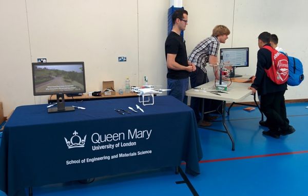
The screen on the left in the figure was to play a movie prepared before an event and it is available under this link:
Link to movie 1
The movie was to assist the presentation and show how the quadcopter flies and propellers perform. The intermediate part of the movie presents quantitative analysis of propellers 1, 4 and 5 (see figures below), obtained through an experiment with a use of simple test bench. The movie is concluded with a practical real life application of propellers and presents how much more can the best propeller lift comparing to other two. Note that the movie was prepared for young folks ;-).
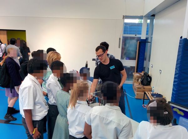
Our presentation starts with gathering group of kids around the blue table. We presented an eye-catching drone asking what makes it possible to fly. Whenever needed, we used a movie to assist our talk. Amongst many important component we focused on propellers. We let kids have a closer look on a set of different propellers and let them guess which will generate highest thrust. The propellers are shown in the figures below. Can you guess which one generates highest thrust :-)?
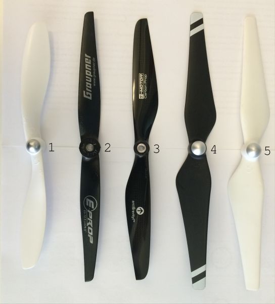
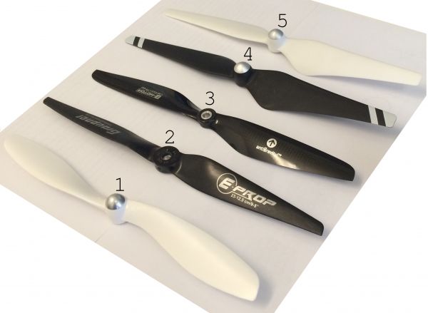
An expert could probably guess that it is either option 4 or 5, however between those two the choice is very hard. There are only small differences, which are often overlooked by a human eye. Ok, enough guessing, lets show what would an engineer or researcher do!?
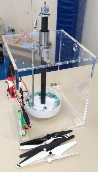
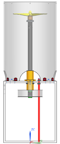
One of the method that engineers use to check performance of designed object is an experiment. For this purpose the propeller test bench was designed and manufactured by our group. The concept was to create a device that allow to easily test different propellers and show a results in an intuitive and simple way. The final design is presented on figures. The bench was designed using a CAD tools (Computer Aided Design). During the event each propeller was tested by checking how many marbles can it lift. Marbles were placed in the white bin as shown on figure below. After this test the 'winner' propeller was presented to kids and explained.
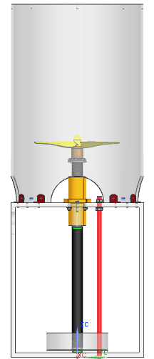
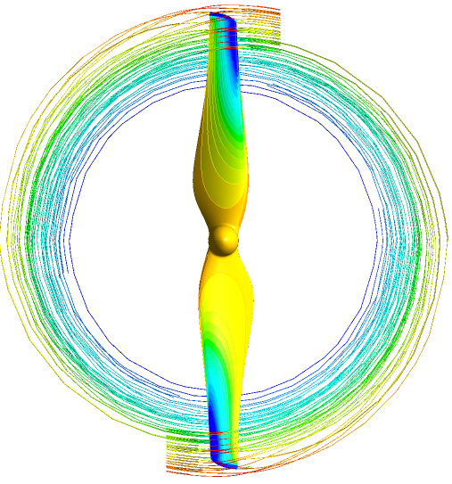
After the experimental part, kids were explained that the practical tests, even though very entertaining and useful, in real life are very expensive. Especially for large objects, like cars, jet engines or airlanes. That is why in modern design process, engineers use computer programs and algorithms to model object and its behviour virtually. These programs, amongst which one is developed by our group, are capable to improve objects of interest - e.g. propeller presented, even when we already have a very good design. Experiments are usually done only for final virtual design to save product development costs.
At the end young folks could use their knowledge to pick the right setup for virtual quadcopter in 'Game of Drones' and try to score as many points as possible.
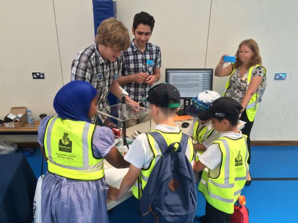
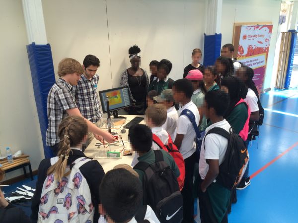
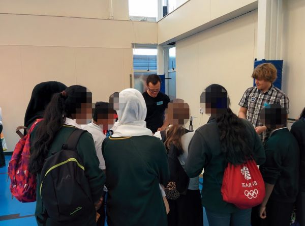
Photos from The Big Bang.
Homework
Ask five engineers why an aircraft flies, and count the number of different answers you get.


