
Test Case 3: TU Berlin TurboLab Stator
The "TurboLab Stator" is a stator in a measurement rig at the TU Berlin in the TurboLab at the Chair for Aero Engines. A model of the stator assembly is shown below. An initial stator geometry has been designed based on a representative stator geometry as used in modern jet engine compressors. This initial geometry has to be optimized to reduce the total pressure loss over different operating conditions. A CAD model of the stator can be downloaded in different formats here: iges, step, parasolid.
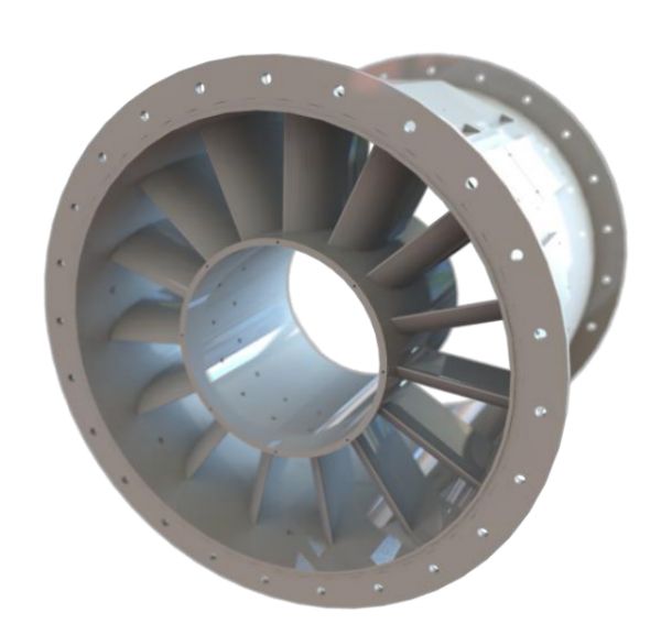
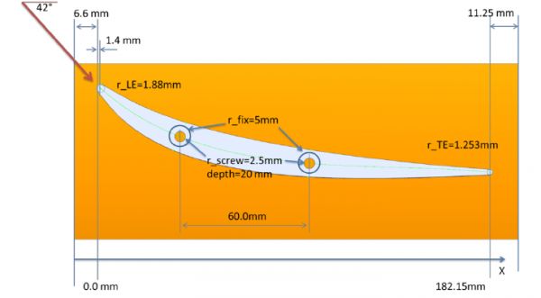
The flow entering the stator has an inlet angle of 42 degrees from axial, uniform over the span. The profile is required to turn the flow to the axial direction. No experimental data are available at this stage. In the figure below a top view is given on the stator vane.
Optimization test cases
Two test cases are considered, one dealing with a single operating point and one considering 3 operating points. In both cases the same degrees of freedom are given to the shape. A large variation is allowed on the profile 3D shape as well as on the hub endwall. Constraints are imposed mainly for manufacturing reasons, including:
- number of blades needs to remain fixed at 15
- axial chord of the blade remains fixed
- thicknes of the blade is restricted: minimum radius at leading and trailing edge is 1 mm and room needs to be foreseen for fixing the blade in the test rig, see figure above.
- the blade needs to be mountable on a rectangular plate of 200mm x 80mm
- the hub endwal contouring needs to remain within the blade passage
For more details on the constraints please consult the detailed description at the bottom of this page.
Test case 1
In the first test case the nominal operating point is considered with 42 degress of swirl. The outlet static pressure is adjusted to keep the mass flow at 9.0 kg/s. Two objectives are considered:
- Minimize the total pressure loss in the stator
- Minimize the deviation from axial flow at the stator exit
Test case 2
The nominal operating point is extended with two off-design conditions, one with 47 degrees of inlet swirl and one with 37 degrees of inlet swirl. In all three operating conditions the static exit pressure is adjusted to maintain a mass flow of 9.0 kg/s. The same objectives are considered as in the first test case, but weighted over the three operating points. 50% of weight is given to the nominal operating point (42 degree swirl), while 25% weight is given to each off-design condition:
- Minimize the weighted total pressure loss in the stator
- Minimize the weighted deviation from axial flow at the stator exit
Detailed description of the test case
A more detailed description of the test case can be found here. Please note that with your registration you agree that your optimal shape(s) will be made available to the Chair of Aero Engines of TU Berlin for testing, pending availability of funding. The submitted optimal shapes will be ranked according to the criteria outlined in the pdf document.
Geometry downloads